
Key takeaways: CATIA V5 Enhanced Scenes let you save nominal and exploded assembly positions without changing the original assembly configuration. Partial Overload Mode captures only the modified components, while Full captures the complete assembly state. With 3DCS, updating the model after switching scenes moves the associated points, features and meshes to the new part positions.
How to Create an Exploded View with Enhanced Scenes in CATIA V5
An Enhanced Scene in CATIA V5 is a set of positions for an assembly. This tool works alongside 3DCS, creating the assembly at a nominal starting position or defining an exploded position for a 3DCS model.
This guide covers how to create an Enhanced Scene in CATIA V5 and how to use it with a 3DCS model.
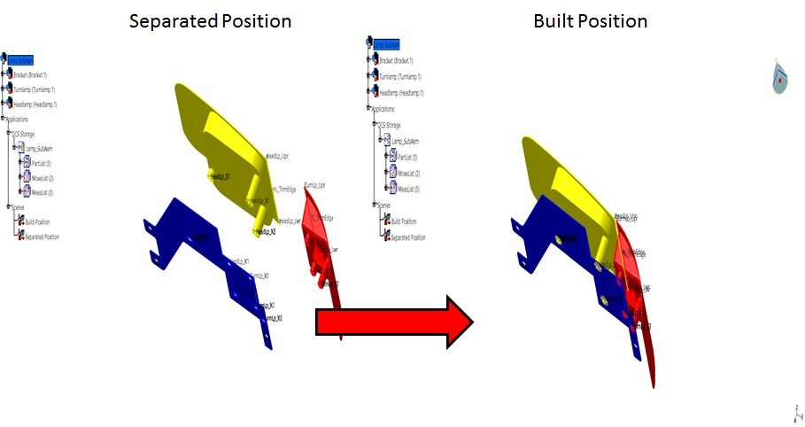
Making a Scene in CATIA V5

- Begin by opening a new model.
- Switch the workbench in CATIA to Assembly Design, if not already active.
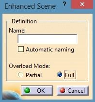
- Select Enhanced Scene on the Scenes Toolbar.
- Naming: you can specify a name for a scene, for example Translated Position, or let CATIA V5 create a generic one.
- Automatic naming: CATIA creates a generic name such as Scene_1.
- Deactivating automatic naming lets you name the scene yourself.
- Overload Mode: this option lets you create a scene with just the translated parts or with the entire assembly.
- Partial: captures only the parts that have been translated or positioned differently from their nominal or design position.
- Full: captures every part in the assembly.
- Once the window switches, exit the scene to save it in CATIA V5. Before exiting, you can still modify the position of the parts within the scene.
Swapping between Scenes
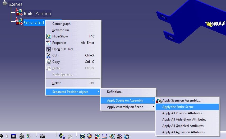
Once multiple scenes have been created, you can switch between them. If 3DCS features already exist in the model, select Update Model and the points, features and mesh will move to the new location of the parts.
To swap between scenes, right-click a scene in the CATIA tree, highlight the Scene Object, highlight Apply Scene on Assembly and select Apply the Entire Scene.
What about making a Scene in 3DCS?
With 3DCS and Enhanced Scenes, the possibilities are wide open. Here are suggestions other modelers have used with 3DCS:
- Create a Design Position scene and a Translated Position scene, then slide between them to check for errors and verify the design was met. This is a useful way to catch positioning issues before they propagate into a drawing or draft for manufacturing.
- Apply a move to your 3DCS model, save the new position as a scene, then switch back to the design position scene to see whether any issues appear in the model or the design.
- Use a scene to isolate selected components by hiding or showing parts, or by changing visual properties such as color and edge thickness.
- Save a specific sample from the model’s simulation. Start with Show Samples, select one of the samples, set the part position and save it as a scene.
FAQ about CATIA exploded view
How do you create a CATIA exploded view using Enhanced Scenes in CATIA V5?
To create a CATIA exploded view using Enhanced Scenes, open your assembly in the Assembly Design workbench and move the parts to the desired exploded positions. Then select Enhanced Scene from the Scenes Toolbar to capture that configuration as a named scene. You can switch back to the nominal position at any time by applying the corresponding scene, and 3DCS features will update automatically when you select Update Model.
What is the difference between Partial and Full Overload Mode when you create a scene for an exploded view?
When you create a scene for an exploded view in CATIA V5, Partial Overload Mode stores only the parts that were explicitly moved, keeping the scene lightweight and focused on the changes. Full Overload Mode records the position of every component in the assembly, which is useful when you need a complete snapshot of the entire configuration. Use Partial when you only need to capture components moved from their nominal position, and Full when the scene needs to capture the complete assembly state.
Find more tips and tactics on the Metrologic DCS Expert Blog.
Questions about 3DCS or CATIA integration? Request a no-cost consultation and talk to one of our application engineers.