Manufacturing Simulation Takes Tolerance Analysis to the Next Level
Tolerance Analysis often refers to just part tolerance stacks, leaving out a large piece of the big picture
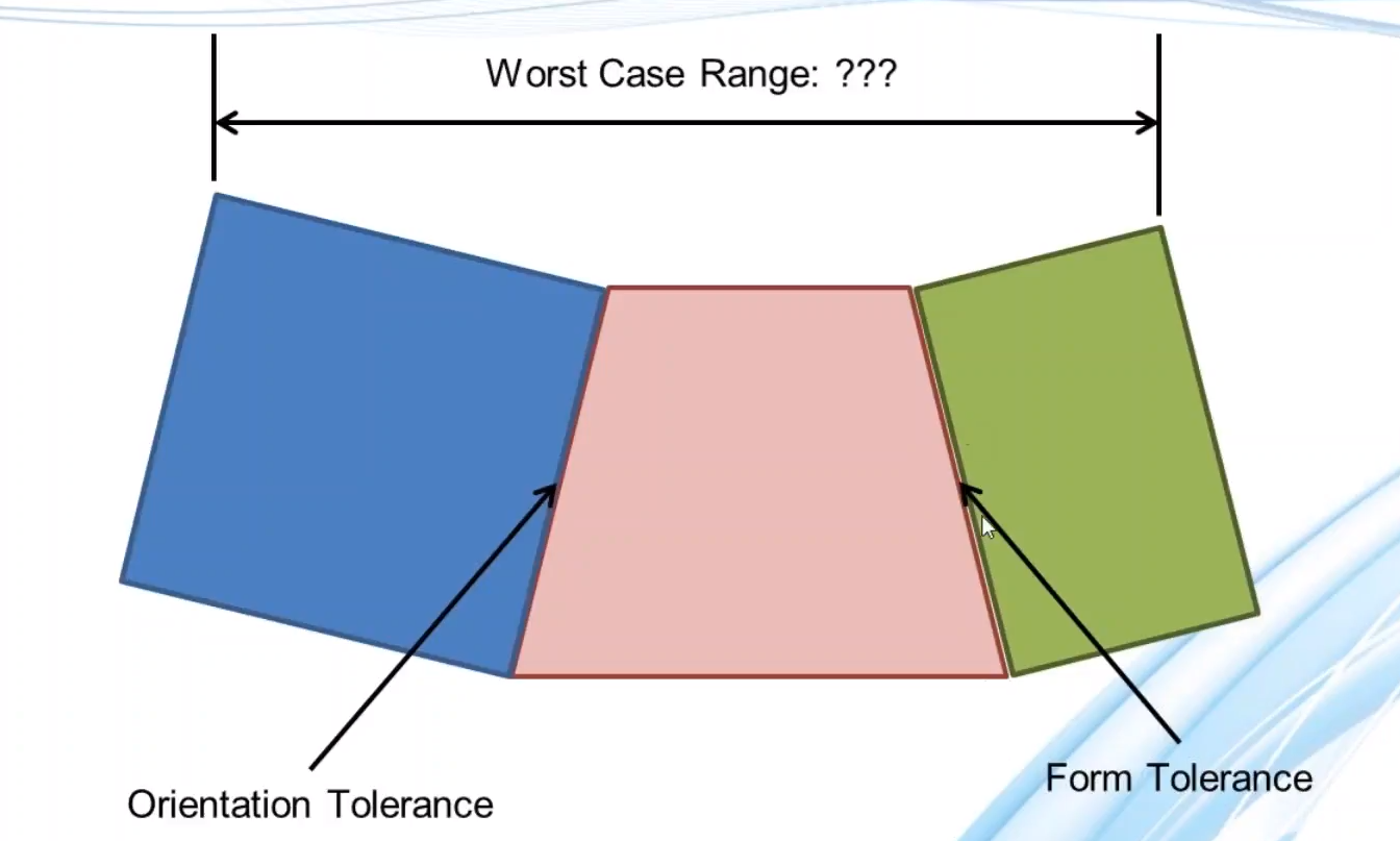
Common tolerance analysis determines the combined variation from a series of interconnected parts in a one-dimensional or two-dimensional stack, such as below. Done commonly in Excel, these analyses are excellent for quick answers and simple assemblies. They do fall short quickly when you need to consider larger number of components, parts in three-dimensional configurations, and of course, starting over every time there is a design change or different output needed. The example below also depicts some complications with even a basic one dimensional stack.
![]()
So What? What Does This Have to Do With Manufacturing Simulation?
Manufacturing Simulation is the consideration of the assembly process and manufacturing processes used on the parts and assembly.
This is important, as the assembly sequence can add variation, the use or lack of use of fixtures and tooling can alter tolerances and add or reduce variation, and of course, manufacturing processes of fixing components together can change their position, deform them, and cause other variation.
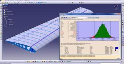 Here’s an example. You rivet the skin of this aircraft wing down to the ribs and stringers. As you rivet the skin, it begins to stretch. Does the aircraft skin have less variation if you start at both ends and rivet it towards the center, or do you start on one side and rivet to the other? If so, which side would be best to start on? These manufacturing processes and sequences can cause a lot of variation in the final product, and are routinely left out of stack studies.
Conditional Logic Accounts for Possible Situations
Tolerance stack ups often consider only the final assembly position. This snap shot of the final parts does not include conditional elements that can occur during assembly or operation. These if/then conditions can occur some of the time, but not necessarily 100% of the time during assembly. This puts an inherent risk of failure into the assembly, which occurs only under certain conditions. Understanding the risk of these conditions can be important in predicting issues at the plant and resolving them early.
Multi-Stage Modeling in an Integrated Solution
Additional variation from manufacturing processes can take the form of multiple assembly stages. Do the components get placed in fixtures for welds before attachment in the final assembly? Does it require a best fit scenario? !D stacks and vector loop analysis do not take these additional factors into consideration and can therefore give an incomplete answer.
Being able to simulate your build through different stages allows for the inclusion of both additional variation from previous steps as well as reduction in variation from the use of tooling and fixtures. Modeling these steps can accurately predict the variation from your production line, rather than just the stacked parts in your final assembly. Interested in seeing this kind of analysis first hand?
See 3DCS for SOLIDWORKS — On-Demand